Two gear pumps can look nearly identical while differing in rotation, displacement, shaft geometry or pressure capability. Build a replacement specification from the installed unit and machine requirements before comparing quotations.
Identify the mechanical interfaces
Photograph the nameplate, mounting flange, shaft and ports. Record dimensions from a drawing where possible. Identify the viewing direction used to describe rotation; a statement of clockwise without a viewing reference can be ambiguous.
Separate flow from pressure
Displacement and speed establish theoretical delivery. Actual delivery is lower because of leakage and varies with operating conditions. Pressure is created by resistance to flow, within the pump's operating limits. Provide continuous duty and any intermittent peaks separately.
Include the inlet and drive conditions
A replacement must suit the fluid, temperature, inlet conditions and drive arrangement. Do not assume a matching flange permits belt loads or other external shaft loads. Obtain confirmation for the complete model code and review the original reason for failure before installation.
Practical checklist
- Document displacement, speed range and rotation reference.
- Provide shaft, flange and port drawings.
- State continuous pressure, peak duty and fluid conditions.
Discuss your application
Explore related hydraulic products, or send JIUDING your model code and application details. Include the circuit drawing and the operating conditions relevant to the checks above so the required configuration can be reviewed.
Further reading
Danfoss: Lumi Group 2 technical information (model-specific example). Manufacturer information applies to the products it identifies; it does not establish JIUDING product ratings or interchangeability.
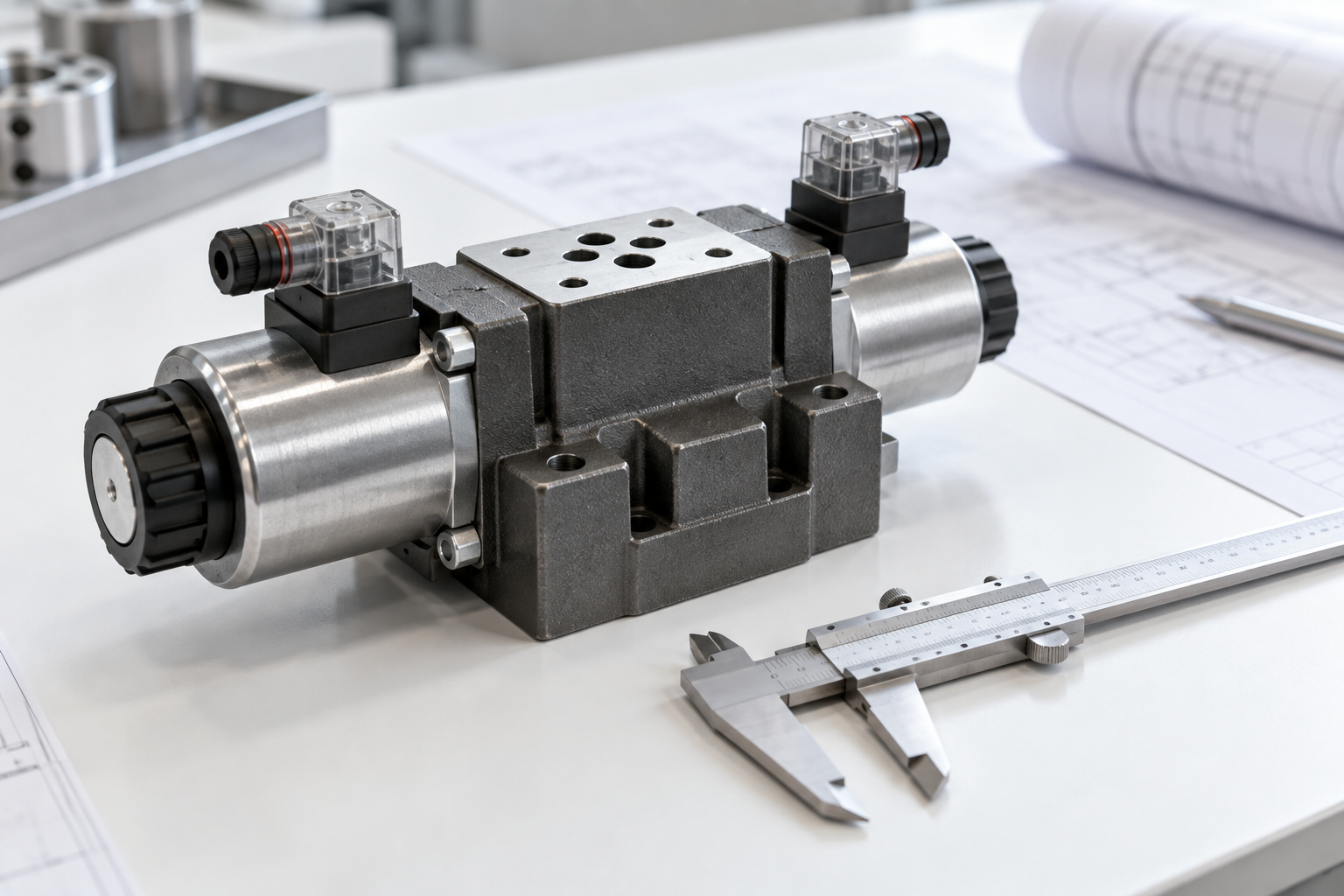
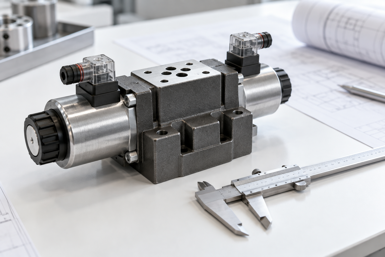
Cover image: AI-generated editorial illustration, not a model-specific product drawing or a photograph of a JIUDING facility.